Handy LED Light Box
What We Are Doing
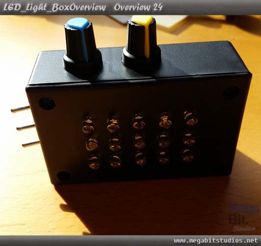
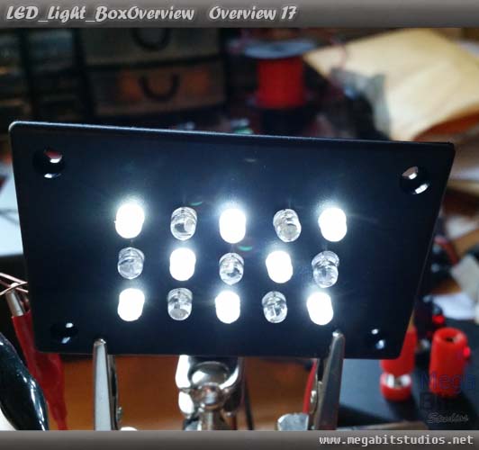
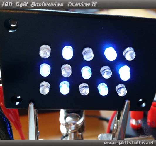
we are going to make a light box that is black light or white light box which has adjustable strobe function and adjustable brightness lamp, all in a small compact package.
Parts Needed / Recourses
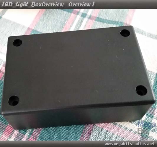
1x Jiffy Box
8x White LED
7x UV LED
1x Length of Single Stranded Wire
1x Spindle Black Cable
1x Spindle Red Cable
1x PCB
3x MicroToggle Switch
4x General Purpose Diodes 1A
2x BC337 NPN Transistor
1x 270R 1W Resistor
2x 1.5KR 0.5W Resistor
1x 20KR 0.5W Resistor
1x 555 Timer
1x 10uF Capacitor
1x 1uF Capacitor
1x 9V Battery
1x 9V Battery Clip
Tools
Drill
Dill Bits
Hot Glue Gun
Soldering Iron
Download
Light Box Circit Board Design
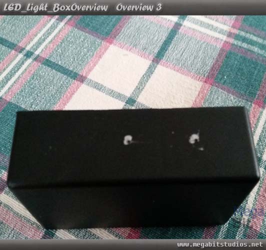
Marking and Drilling
First off work out where you would like everything to be located switches, pots, led, battery and circuit board, make sure your box is big enough to house everything
Start with the LEDs because this can be the hardest to mark out. luck for me the box I chose had a handy pre measured grid so I just selected where I wanted the LEDs to go. if your box doesn't have this you will have to measure and work out everything manually, so for 5mm LEDs you will have to make a 6mm grid them plot out the array you want the leds to be placed.
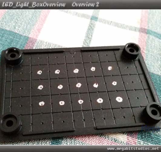
Next work out where you want the potentiometers to go I did mine free hand so if you want your to line up exactly and make sure the components fit I recommend measuring, do the same thing with the switches after marking the holes use a screw driver or a scribe to make an indentation it will make drilling much easier.
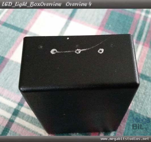
Now simply drill all the marked holes with the appropriates drill bits and clean up the holes when done.
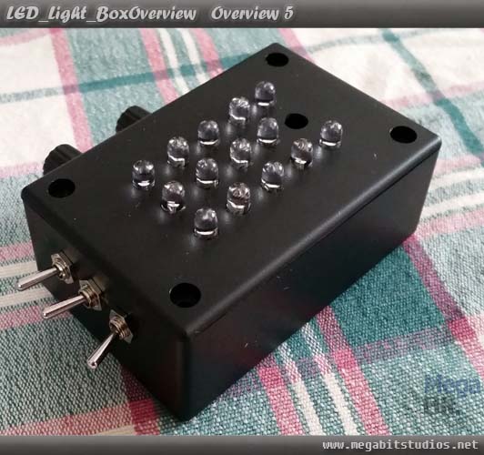
Do a mock up with components in places and make sure you have enough clearance and everything fits in to the box nicely. (note the hole missing is a led I was testing a bigger hole and was to big)
Soldering & Hot Glue
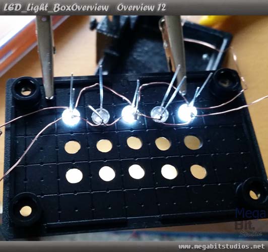
Ok now that we know everything will fit we can start soldering the LEDs in place grab the single core wire and wrap it around the positive leg of the white Led and make sure to leave a bit of overhanging wire this will be the connection to the circuit board.
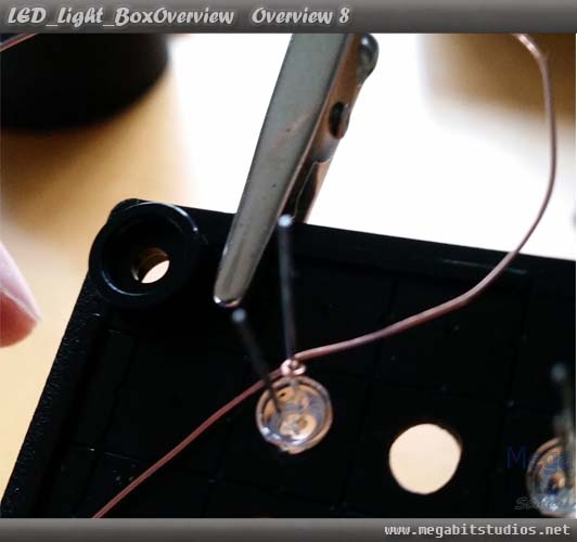
Make sure to push the LEDs to the base the hole and solder the connection, now bend the wire up and around to the next LED leg and repeat for the third one.
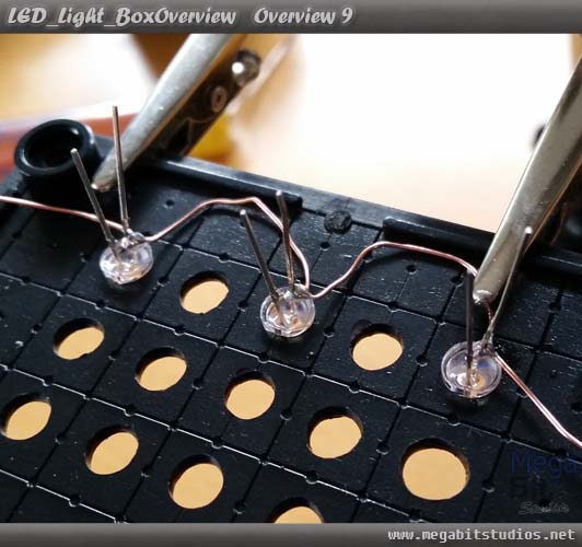
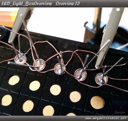
For the negative leg do the same thing but this time we will be working the UV LEDs in as well.
Once all the negative legs are connected it should be looking like this.
At this point test that the connections are working and that led are working repeat this after doing every row of the LEDs.
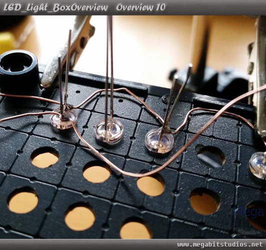
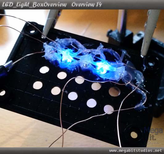
Now for the positive wires for the UV LEDs do the same as the white just make sure the wire for the white LEDs does not short to the UV LEDs wire.
(Note: If the UV and white LEDs are lighting up at the same time you have a short somewhere).
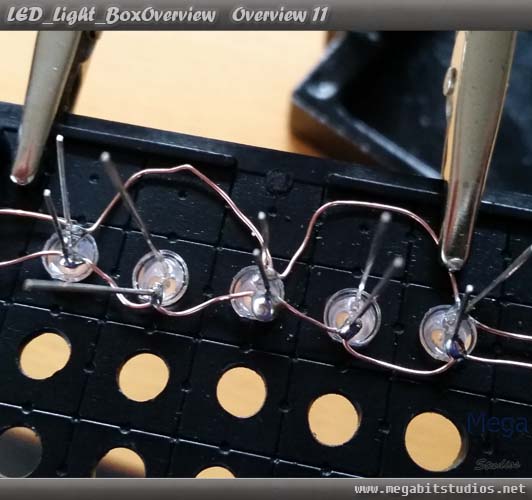
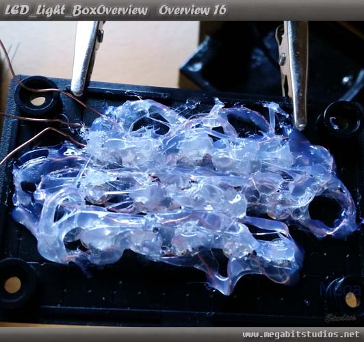
Now to hot glue everything in place making sure nothing is sorting, then trim all the legs of the LEDs. Glue the exposed legs and curve the wires around for the next row. Doing all of this will insulate the LEDs and stop them from shorting, then test that everything is working.
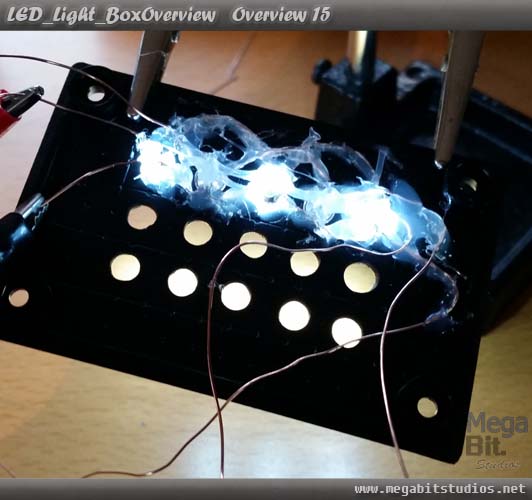
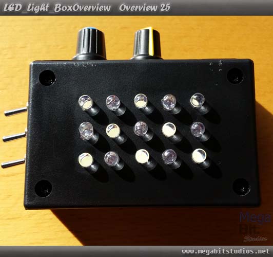
Once you have done all of the rows you should have something like this, to avoid a headache later make sure you tested the rows as you do them, I actual had a dead led and hade to replace it luckily I tested the row before I put the glue over the LEDs so it was easy to replace, one you have done this, cut the leads off the pieces of wire for the positive and negatives of the LED's long enough to open and close the box
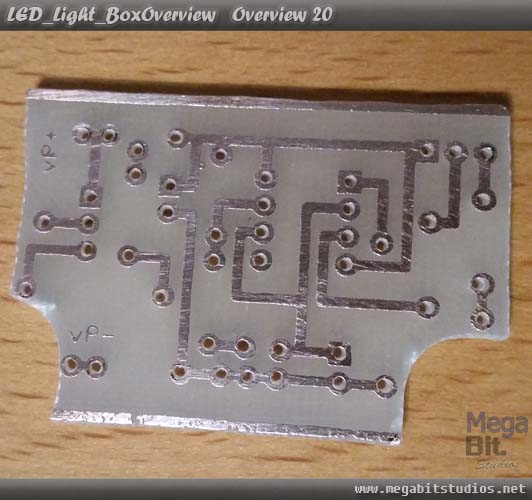
Creating The PCB & Continuing To Solder
Ok now to create the PCB to drive the whole thing, download the circuit board design here (for etching), use you preferred method of creating a PCB may it be a prototype board, PCB etching or milling. We also have how to make your own pcb using the etching method here
Circuit Diagram
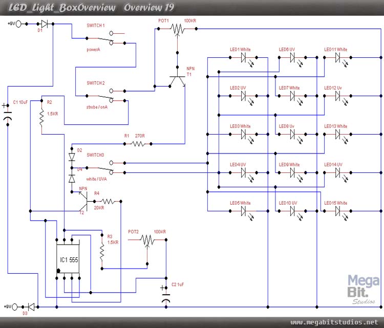
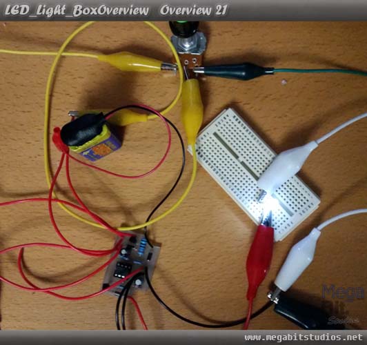
Once you have the board created solder all of the components to it along with enough wire for the inputs and outputs. Once everything is together, test that the circuit is functioning correctly.
Start by putting the PCB in to the case and hot glue it down if required.
Solder a diode to the positive wire of the battery clip, then put a piece of heat shrink over the diode and wire so that it is big enough to cover the whole thing, solder the diode to the centre of the power switch.
Solder a wire to the bottom pin of the power switch put a two peace of heat shrink over the wire to cover the 2 joins, then solder the other side of the wire to the centre of second switch and seal the heat shrink.
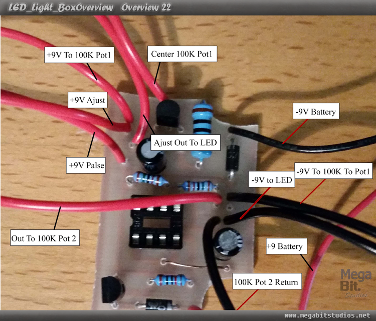
Put a piece of heat shrink over the "+9V Adjust" wire from the circuit board and solder it to the bottom of the of the second switch do the same with the "+9V pulse" but solder it to the top of the second switch.
Solder "Pulse Out to LED" and "Adjust Our to LED" together and solder them to the centre on the third switch, put heat shrink over the UV and White LED's positive leads and solder the UV LED's positive lead to the top of the switch and seal the heat shrink and do the same with the white LED but solder that to the bottom of the third switch.
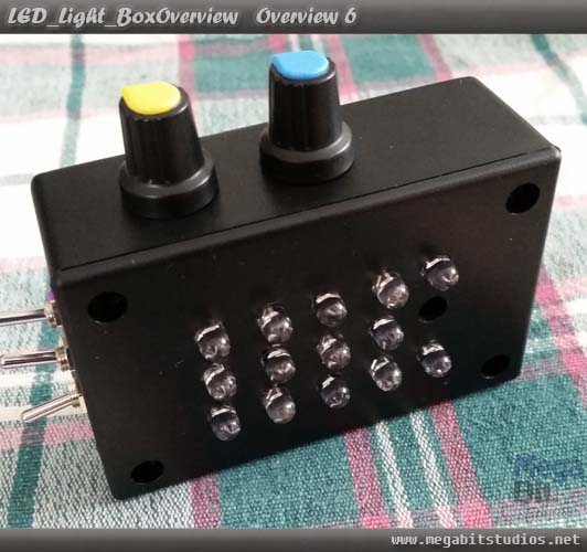
Now to solder the pots start by putting heat shrink over the "+9v to 100k Pot1" wire and solder it to right contact on the first pot and seal the heat shrink, then with the "Centre 100k Pot" wire put some heat shrink over that then solder it to the centre contact of the first pot and seal the heat shrink, with the "-9V To 100K Pot1" wire solder and heat shrink it to the left contact of the first pot.
For Pot 2 Solder and heat shrink the "Out to 100K Pot 2" wire to the centre of the second pot, Do the same with the "100K Pot 2 Return" wire but solder it to the right contact of the 2nd pot
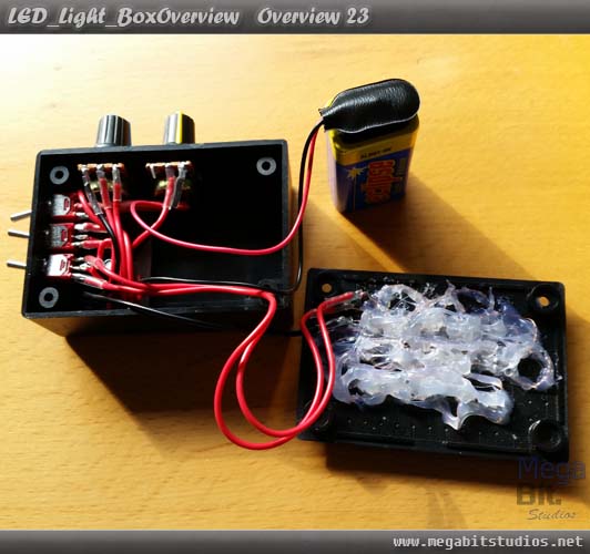
Connect the battery and put everything thing in to the box and close it up and you’re done.